ALTEEM WEB GUIDE- 300 SERIES
High performance web guide system designed to achieve accurate positioning of web at different stages of process. It can be combined with high speed PMDC motorized ball-screw type actuator and for heavy load application servo motor is used to build an automatic edge alignment system.


Key Features

Responsive color Touch Screen

User Friendly UI

Remote Control via Smart Phone

Heavy Duty Actuator Support

Plug n Play Design

OTA Updates and trouble shooting

Low Maintenance

CCD Sensor
Dimensions

Edge guiding system – AEG-300
Alteem’s Edge guide system regulates the ongoing web in various production processes in the printing and packaging industry for different material such as in the film, foil, paper and textile. Having electronic web guide system ensures that material is being processed in the correct direction.
To reduce material wastage at high machine speeds throughout the web, AEG -300 can be installed to correct web position at unwinder, intermediate and at rewinder.

AEG-300 - TECHNICAL DATA
| Display resolution | 480×272(RGB) | ||||||||
|---|---|---|---|---|---|---|---|---|---|
| Display Size | 4.3 Inch Touch Scree | ||||||||
| Operating Mode | Auto/Manual | ||||||||
| Sensor Input | Ultrasonic Sensor | ||||||||
| Input | 0-10VDC | ||||||||
| Alarm |
|
||||||||
| Power Supply | 24VDC/2.1AMP | ||||||||
| Power Consumption | 48W | ||||||||
| Operating Temperature | 0 to 50⁰c | ||||||||
| Dimensions | 155x105x35 |
Ultrasonic Sensor - TECHNICAL DATA
| Model | AUS-102 |
|---|---|
| Sensor Type | Ultrasonic |
| Ideal working distance | 25 mm |
| Measuring Range | ±10 mm |
| Accuracy | 0.1 mm |
| Frequency | 48KHz |
| Input Voltage | 12-24 VDC |
| Power consumption | ≤ 1 Watt |
| Output Voltage | 0-10 VDC |
| Material Which can be detected | Transparent Material, Opaque Material |
| Weight | 300gm |
| Housing | Aluminium Anodised |
| Dimension | 100X40X100mm |
Line guide system ALG -300
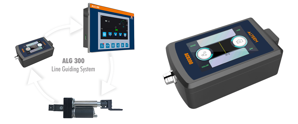
ALG 300 - TECHNICAL DATA
| Display resolution | 480×272(RGB) | ||||||||
|---|---|---|---|---|---|---|---|---|---|
| Display Size | 4.3 Inch Touch Scree | ||||||||
| Operating Mode | Auto/Manual | ||||||||
| Sensor | Opto-electronic / CCD | ||||||||
| Input | 0-5 VDC | ||||||||
| Alarm |
|
||||||||
| Power supply | 24VDC/5AMP | ||||||||
| Power Consumption | 100W | ||||||||
| Operating Temperature | 0 to 50⁰c | ||||||||
| Dimensions | 155x105x34 |
CCD Sensor - TECHNICAL DATA
| Model | ACD300 |
|---|---|
| Sensor Type | CCD |
| Ideal working distance | 30mm |
| Measuring Range | .+-5mm |
| Input Voltage | 12 VDC |
| Output Voltage | 5 V |
| Power consumption | 12W |
| Web Scan | Printed Line, Printed / Transparent Web Edges |
Center guide system ACG -300
The center guide system keeps the center line of the web in an exact position on Blown film extrusion machine. The ultrasonic sensors continuously reposition themselves automatically to detect both web edges and maintain the center line irrespective of any width variation.

Key Features
Vivid Touch Screen Display
Master & Slave Controller For Easy Operation
Linear Positioning System With Timing Belt
Online Width Measurement
0.1mm Sensing Accuracy
Remote Control Via Smart Phone
ACG -300 - TECHNICAL DATA
| Display size | 4.3″ TOUCH SCREEN | |||||||||||||||
|---|---|---|---|---|---|---|---|---|---|---|---|---|---|---|---|---|
| Display resolution | 480×272 | |||||||||||||||
| Color depth | 65K color (16BIT) | |||||||||||||||
| Operating mode | Auto/Manual/Center | |||||||||||||||
| Sensor | Ultrasonic Sensors -02 Nos. | |||||||||||||||
|
|
|||||||||||||||
|
|
|||||||||||||||
| Power supply | 24VDC/5AMP | |||||||||||||||
| Power consuption | 100W | |||||||||||||||
| Operating temperature | 0 to 50⁰c | |||||||||||||||
| Dimension | 155x105x35 |

Key Features
PMDC motorized actuator
High response mechanism with liner screw designed for accurate correction movements
Linear positioning system with timing belt


ACTUATOR BALL SCREW DIMENSION TABLE
| SR.NO. | ACTUATOR MODEL NO. | A | B | C | D | E | F | G | H | I | J | K | L | M | N | O |
|---|---|---|---|---|---|---|---|---|---|---|---|---|---|---|---|---|
| 1 | ACT – 165 – 50 | 70 | 51.5 | 57.5 | 107 | 50 | 53 | 71.75 | 73 | 319 | 385 | 401 | 431 | 459 | 25 | 120 |
| 2 | ACT – 165 – 100 | 70 | 51.5 | 57.5 | 157 | 100 | 53 | 71.75 | 73 | 419 | 485 | 501 | 531 | 559 | 25 | 120 |
| 3 | ACT – 165 – 150 | 70 | 51.5 | 57.5 | 210 | 150 | 53 | 71.75 | 73 | 522 | 588 | 604 | 634 | 662 | 25 | 120 |
| 4 | ACT – 165 – 200 | 70 | 51.5 | 57.5 | 260 | 200 | 53 | 71.75 | 73 | 622 | 688 | 704 | 734 | 762 | 25 | 120 |
| 5 | ACT – 1924 – 100 | 70 | 51.5 | 63 | 157 | 100 | 53 | 71.75 | 73 | 424.5 | 490.5 | 506.5 | 536.5 | 564.5 | 27 | 132 |
| 6 | ACT – 1924 – 150 | 70 | 51.5 | 63 | 207 | 150 | 53 | 71.75 | 73 | 527.5 | 593.5 | 609.5 | 639.5 | 667.5 | 27 | 132 |
| 7 | ACT – 1924 – 200 | 70 | 51.5 | 63 | 257 | 200 | 53 | 71.75 | 73 | 627.5 | 693.5 | 709.5 | 739.5 | 767.5 | 27 | 132 |
| 8 | ACT – 1942 – 150 | 70 | 51.5 | 67 | 207 | 150 | 53 | 71.75 | 73 | 531.5 | 597.5 | 613.5 | 643.5 | 671.5 | 27 | 132 |
| 9 | ACT – 1942 – 200 | 70 | 51.5 | 67 | 257 | 200 | 53 | 71.75 | 73 | 631.5 | 697.5 | 713.5 | 743.5 | 771.5 | 27 | 132 |